-
CODE
STL
Wemos NodeRED
MOBILE PRINTER
Wireless Thermoprinter hacked with a Wemos R1 mini Pro enabled for MQTT NodeRED Communication
Owning the Device
There are many reasons why you would want to have a small, mobile, wireless printer. The problem I had with this printer was, that it would only work with a Windows-software (lul) or a closed source iOS App via Bluetooth. While taking over control of the device via the Bluetooth-Gateway was possible, I had not the hardware and skills to dive into the messed up world of BT pairing. I found it easier to own the device by its COM-Port on the front of the device. Sadly, the "manual" was of no help regarding the pinout and the commands. But I read from the Datasheet of the Chip used inside the device, that it understands EIA/TIA-232-F Standards. That is useful. That I can do.

ZJ-5802LD Thermo Printer
With a name only a manufacturer could love, I found this device that matched my price range (50$+-10) and was battery powered. The target seems to be flying mechants on fairs and markets to print out receipts or QR-Codes for transactions
Tell me about you
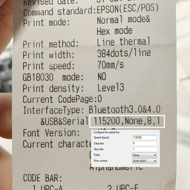
You can print out a Test-Page from the iOS App. This will give you a long list of used character sets but also some informations about the interface configuration.
RS-232, do you speak it?
I certainly dont and most USB-Serial Converter go straight to TTL. Lucky if you have a set of TTL-RS232-converter around. People born before 1990 have a good chance for that. RS-232 is pretty common to encounter in the wild.
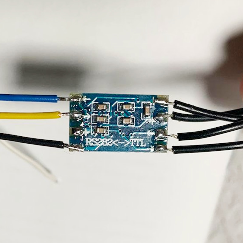
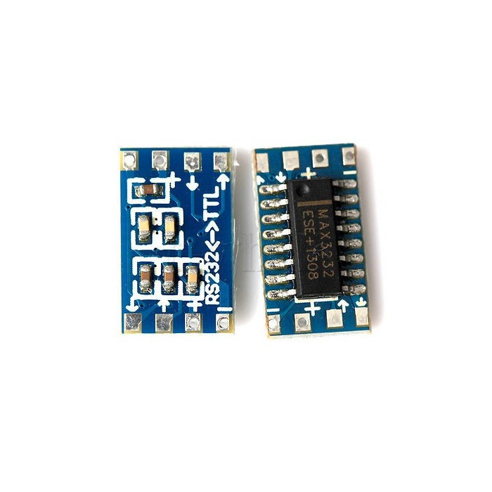
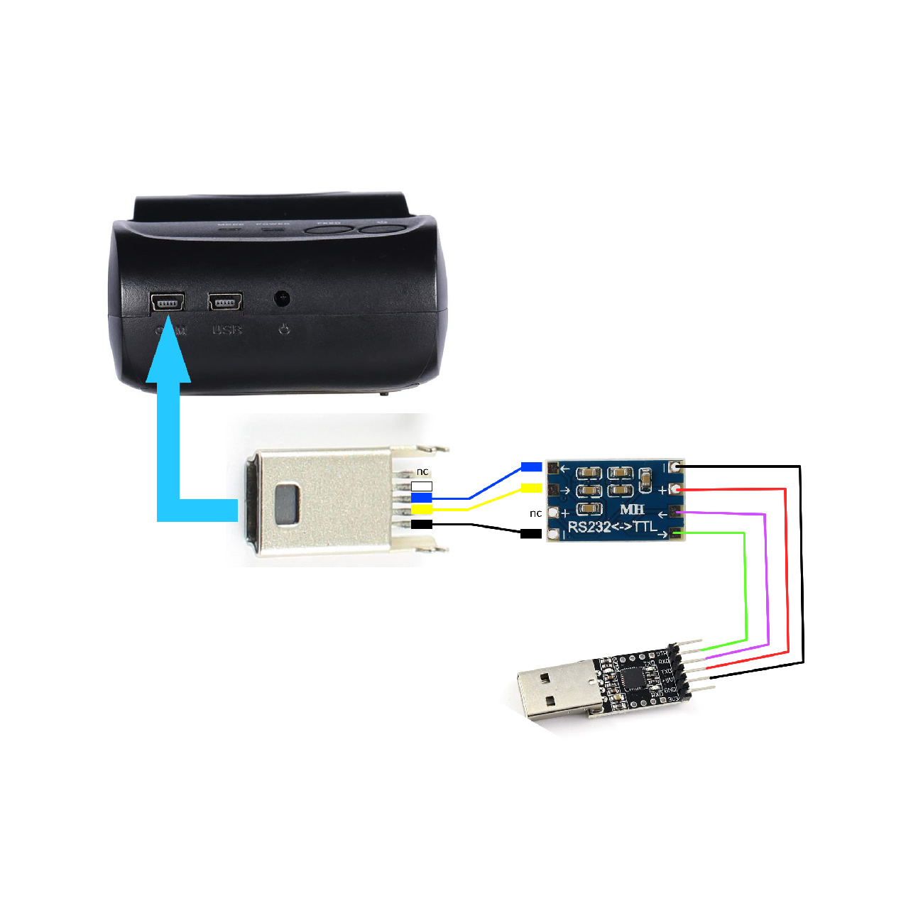
From TTL to RS-232
The wiring is straight forward. On the RS-232 side, you only need the (blue) out cable and GND. The device will not talk back apparently hence yellow is not a must. I would not advice connected also the 5V rail. It is not worth the risk.
Finding the Pinout
While the printer does have a mini-USB COM-Port, it was not clear what pins were used in the RS-232 configuration. Normaly USB has a VCC,D+,D- and GND. The RS-232 standard can have up to 9 Pins. So how was the 4Pin USB-Port used for the RS-232 purpose? To find the correct pinout I had to open the case, trace the signal lines to the correspondig chip and from there were able to figure out what pin was used for what. While VCC and GND were used like in a normal USB configuration, the remaining 2 pins (or 3, if you count the ID Pin too) were used for T1OUT, T2OUT and R1IN (as expected). While the chip received all my commands, it never gave anything back. I dont know why they even connected TWO(!) TXOUT lines at all. But RS-232 allowes to only listen. There is no need for feedback. Maybe it is a factory setup test thing. I dont have the command-list to trigger anything out.
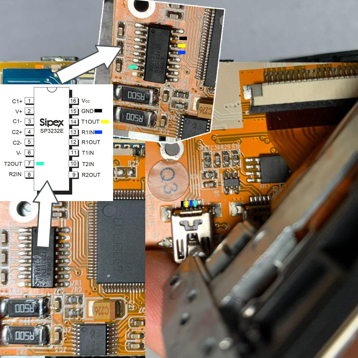
Reverse engeneering pinout
Diving into the printer, finding the chip, finding the Datasheet, continuity testing the connections, and getting the pinout

USB to TTL Serial Converter
A simple USB to TTL Converter will not work, as you also need an additional TTL to RS232 circuit for that as well.

Soldering cables
We want to break out the R1IN Pin as well as the GND Pin for our external usecase and skip the mini USB COM-Port. We also tap into the battery terminal to power our Wemos board by stepping the 7.4V down to 5V
The USB Port
In the debug-stage I got my first working prototype with this setup. In the later revision I tapped directly into the chip and went from there, but I wanted to make first sure, by conecpt works on a breadboard.
The Code
I traced them back until Lorem ipsum dolor sit amet nisl sed nullam feugiat Lorem ipsum dolor sit amet nisl sed nullam feugiat Lorem ipsum dolor sit amet nisl sed nullam feugiat Lorem ipsum dolor sit amet nisl sed nullam feugiat
software_serial.ino
Software serial multple serial test

┌───────────────────────────────────┐
│    __  __  ___               ╔═════════════════╦═════════════════╗
│   |  \/  |/ _ \              ║ 1st Published:  ║ Last Edit:      ║
│   | |\/| | (_)|              ║ 14.01.2019      ║ 20.08.2021      ║
│   |_|  |_|\___/ _  _____     ╚═════════════════╩═════════════════╝
│   |  \/  | /_\ | |/ / __|    ┌────┴──────────────────────────────
│   | |\/| |/ _ \| ' <| _|     │ Author : Mo
│   |_|  |_/_/_\_\_|\_\___|    │ Credits: Tom Igoe,  Mikal Hart
│   |  \/  |/ _ \| _ \ __|     ├──────────────────────────────
│   | |\/| | (_) |   / _|      │ ▓▒░ MoMakeMore.com
│   |_|  |_|\___/|_|_\___|     └────┬───────────────
│                                   │
└───────────────────────────────────┘
*/

/*
* Getting Started example sketch for nRF24L01+ radios
* This is an example of how to send data from one node to another using data structures
* Updated: Dec 2014 by TMRh20
*/

#include  //Lib by
#include  //Lib by

byte addresses[][6] = {"1Node","2Node"};


/****************** User Config ***************************/
/***      Set this radio as radio number 0 or 1         ***/
bool radioNumber = 1; //1 = Sending, 2= Receiving

/* Hardware configuration: Set up nRF24L01 radio on SPI bus plus pins 7 & 8 */
RF24 radio(9,10);
/**********************************************************/


// Used to control whether this node is sending or receiving
bool role = 1;

/**
* Create a data structure for transmitting and receiving data
* This allows many variables to be easily sent and received in a single transmission
* See http://www.cplusplus.com/doc/tutorial/structures/
*/
struct dataStruct{
  unsigned long _micros;
  float value;
}myData;

void setup() {

  Serial.begin(115200);
  while (!Serial) ;
  Serial.println(F("RF24/examples/GettingStarted_HandlingData"));
  Serial.println(F("*** PRESS 'T' to begin transmitting to the other node"));

  radio.begin();

  // Set the PA Level low to prevent power supply related issues since this is a
 // getting_started sketch, and the likelihood of close proximity of the devices. RF24_PA_MAX is default.
  radio.setPALevel(RF24_PA_LOW);

  // Open a writing and reading pipe on each radio, with opposite addresses
  if(radioNumber){
    radio.openWritingPipe(addresses[1]);
    radio.openReadingPipe(1,addresses[0]);
  }else{
    radio.openWritingPipe(addresses[0]);
    radio.openReadingPipe(1,addresses[1]);
  }

  myData.value = 1.22;
  // Start the radio listening for data
  radio.startListening();
}


void loop() {


/****************** Ping Out Role ***************************/
if (role == 1)  {

    radio.stopListening();                                    // First, stop listening so we can talk.


    Serial.println(F("Now sending"));

    myData._micros = micros();
     if (!radio.write( &myData, sizeof(myData) )){
       Serial.println(F("failed"));
     }

    radio.startListening();                                    // Now, continue listening

    unsigned long started_waiting_at = micros();               // Set up a timeout period, get the current microseconds
    boolean timeout = false;                                   // Set up a variable to indicate if a response was received or not

    while ( ! radio.available() ){                             // While nothing is received
      if (micros() - started_waiting_at > 200000 ){            // If waited longer than 200ms, indicate timeout and exit while loop
          timeout = true;
          break;
      }
    }

    if ( timeout ){                                             // Describe the results
        Serial.println(F("Failed, response timed out."));
    }else{
                                                                // Grab the response, compare, and send to debugging spew
        radio.read( &myData, sizeof(myData) );
        unsigned long time = micros();

        // Spew it
        Serial.print(F("Sent "));
        Serial.print(time);
        Serial.print(F(", Got response "));
        Serial.print(myData._micros);
        Serial.print(F(", Round-trip delay "));
        Serial.print(time-myData._micros);
        Serial.print(F(" microseconds Value "));
        Serial.println(myData.value);
    }

    // Try again 1s later
    delay(1000);
  }


/****************** Pong Back Role ***************************/

  if ( role == 0 )
  {

    if( radio.available()){
                                                           // Variable for the received timestamp
      while (radio.available()) {                          // While there is data ready
        radio.read( &myData, sizeof(myData) );             // Get the payload
      }

      radio.stopListening();                               // First, stop listening so we can talk
      myData.value += 0.01;                                // Increment the float value
      radio.write( &myData, sizeof(myData) );              // Send the final one back.
      radio.startListening();                              // Now, resume listening so we catch the next packets.
      Serial.print(F("Sent response "));
      Serial.print(myData._micros);
      Serial.print(F(" : "));
      Serial.println(myData.value);
   }
 }


/****************** Change Roles via Serial Commands ***************************/

  if ( Serial.available() )
  {
    char c = toupper(Serial.read());
    if ( c == 'T' && role == 0 ){
      Serial.print(F("*** CHANGING TO TRANSMIT ROLE -- PRESS 'R' TO SWITCH BACK"));
      role = 1;                  // Become the primary transmitter (ping out)

   }else
    if ( c == 'R' && role == 1 ){
      Serial.println(F("*** CHANGING TO RECEIVE ROLE -- PRESS 'T' TO SWITCH BACK"));
       role = 0;                // Become the primary receiver (pong back)
       radio.startListening();

    }
  }


} // Loop


┌──────────────────────────────┐
│ © MoMakeMore.com // Mo 2021  │
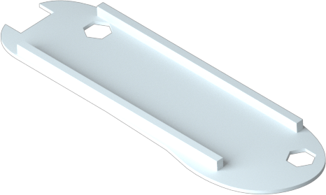
Make it look good!
While some might stop here and toss their breadboard into their success-project-bin, I like to make the solution as integrated and invisible as possible. For that, I use my trusty 3D-Print to create a PLA housing. The Solution I cam up with has 3 Parts: A leveling layer to align the 3D printed part near seamless to the printer itself. Second a carrier board, to hold the wemos, the step down and the RS-232 converter in place. And Lastly a goold old fashioned outer shell for protection of shorts and dust and stuff.
white